


 TV antenna from a computer disk drive plate (part 2)
 Decimeter waves wire antenna
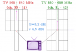
 TV antenna from a computer disk drive plate
 Dimensions of the Kharchenko "Web" broadband antenna for FM and VHF bands
 Dimensions of the 5-element Uda-Yagi antenna for the FM range 87.5-108 MHz
Languages
Theme
Popular tags
Random post
Archive of posts
- July 2026 ✒ 13
- June 2026 ✒ 8
- May 2026 ✒ 2
- April 2026 ✒ 6
- March 2026 ✒ 3
- February 2026 ✒ 7
- January 2026 ✒ 8
- December 2025 ✒ 12
- November 2025 ✒ 9
- October 2025 ✒ 8
- September 2025 ✒ 5
- August 2025 ✒ 8
- July 2025 ✒ 6
- June 2025 ✒ 10
- May 2025 ✒ 4
- April 2025 ✒ 4
- March 2025 ✒ 4
- February 2025 ✒ 11
- December 2024 ✒ 8
- November 2024 ✒ 2
- October 2024 ✒ 8
- September 2024 ✒ 3
- August 2024 ✒ 5
- July 2024 ✒ 9
- June 2024 ✒ 6
- May 2024 ✒ 7
- April 2024 ✒ 5
- March 2024 ✒ 5
- February 2024 ✒ 5
- January 2024 ✒ 6
- December 2023 ✒ 7
- November 2023 ✒ 4
- October 2023 ✒ 8
- September 2023 ✒ 7
- August 2023 ✒ 4
- July 2023 ✒ 7
- June 2023 ✒ 7
- May 2023 ✒ 5
- April 2023 ✒ 6
- March 2023 ✒ 5
- February 2023 ✒ 2
- January 2023 ✒ 5
- December 2022 ✒ 7
- November 2022 ✒ 8
- October 2022 ✒ 6
- September 2022 ✒ 9
- August 2022 ✒ 8
- July 2022 ✒ 4
- June 2022 ✒ 9
- May 2022 ✒ 7
- April 2022 ✒ 3
- March 2022 ✒ 4
- February 2022 ✒ 6
- January 2022 ✒ 7
- December 2021 ✒ 7
- November 2021 ✒ 7
- October 2021 ✒ 7
- September 2021 ✒ 10
- August 2021 ✒ 6
- July 2021 ✒ 7
- June 2021 ✒ 7
- May 2021 ✒ 7
- April 2021 ✒ 4
- March 2021 ✒ 4
- February 2021 ✒ 3
- January 2021 ✒ 4
- December 2020 ✒ 8
- November 2020 ✒ 2
- October 2020 ✒ 3
- September 2020 ✒ 3
- August 2020 ✒ 5
- July 2020 ✒ 5
- June 2020 ✒ 8
- May 2020 ✒ 10
- April 2020 ✒ 4
- March 2020 ✒ 2
- January 2020 ✒ 1
- December 2019 ✒ 2