29
October
2021
Wi-Fi router antenna design and MMANA model
16:22

Wi-Fi router antenna design and MMANA model

29 October 2021 16:22

At work I was given a “new” ADSL router. Among the useful things in it are a 19-volt power supply and antennas.
I disassembled the antenna (the router is stated as dual-band 2.4 and 5 GHz) to look at the design...

Under the plastic casing of the router antenna there is a regular coaxial dipole made of two brass tubes.
They are connected by a rigid heat-shrinkable tube, under which there is a power supply unit.

ant-wifi

Shoulders 27 mm upper part, 20 mm lower ("glass"), gap 5 mm. For such a dipole, the braid is connected to the lower tube (which performs the BalUn 1:1 function), and the cable core is connected to the upper one.

I created a model in the MMANA electromagnetic modeling program, the calculation of which confirmed that the antenna has a resonance at a frequency of 2.4 GHz (for Wi-Fi) and is quite broadband - it covers the range of 2150-2600 MHz in terms of SWR<2.
risunok
graphic

Work on the second and third harmonics

4800 MHz (second harmonic) - SWR=3.8 (Z = 100 - j88.29).
5600 MHz (Wi-Fi 5 GHz) - SWR=3.6 MHz (Z = 85 - j82). When using a plastic screen, the resonance frequency will shift down and you can expect SWR = 1.7
7200 MHz (third harmonic) - SWR=1.42 (Z=63 - j15). Good agreement.

Size ratio

Size mm λ
Overall length 54 0.416
Tube Diameter 4 0.032
Upper (long) shoulder 27 0.216
Interval 5 0.04
Lower (short) shoulder or "glass" 20 0.16

It can be seen that for some reason the length is not 0.5 wavelength, but only 0.416 lambda. The thickness of the tube affects it. Also, I did not take into account the influence of the dielectric of the external plastic antenna cover. Apparently, the SWR in reality is about 1.2 in the Wi-Fi range, as in the model. The dielectric of the antenna shell may shift the resonance frequency downwards, towards lower frequencies.

The influence of antenna dimensions on the complex input impedance of the antenna

Let us examine this dipole of an asymmetrical design. By changing the dimensions of the dipole arms within small limits, you can observe the change in the input resistance.

  1. Increasing the long arm by 1mm while shortening the short arm by 1mm -
  • increases input impedance by 1 ohm
  • shifts the resonance frequency up (-j1)
    1. Shortening the long arm by 1mm and lengthening the short arm by 1mm
      *reduces input impedance by 0.7 Ohm
  • shifts resonance down (+j0.57)
    1. Increasing the circle diameter (tube diameter) of the antenna by 5%
  • slightly lowers the resonance frequency (+j0.6)

145 MHz/435 MHz Antenna Scaling and Simplification

Why might this antenna be of interest to radio amateurs? For example, by scaling the antenna to 435 MHz and 145 MHz based on the principle of similarity.
Instead of a metal tube, you can use a set of wires. Further simplification: we get rid of the third dimension - thickness.
There is a wire, flat antenna made of two rectangles. Which was later optimized in the MMANA program.

option 1:
top rectangle 435 x 160,
bottom rectangle 311 x 160,
the distance between them is 33 mm.
motiff

Gain at 145 MHz is 2.11 dbi, SWR is no worse than 1.2 in the range of 144-146 MHz. SWR is shifted to 146 MHz.
Gain at 438 MHz - 5.0 dbi, SWR about 1.5 in the range 430-440 MHz
dn
SWR 144
swr1
SWR 435
swr2

option 2:
top rectangle 459 x 170,
bottom rectangle 313 x 170,
the distance between them is 16 mm.

var2
var2swr1
var2swr2

Both options are equivalent in terms of parameters: the gain and matching are the same. The polarization is vertical (the horizontal component of the radiation is practically absent).

Material - wire of any diameter. The cable braid is attached to the lower rectangle, and the core to the upper.
Setting: by bringing two rectangles closer together. The approximate dimensions of the antenna are 0.46 by 0.17 meters.

MMANA models - original antenna at 2400 MHz and wire antenna at 145/435 MHz (2 options):
mmana_wifi_145_435.zip

Antenna for FM range 88-108 MHz

The antenna was further scaled to the FM broadcast band.
Where I performed size optimization, which made it possible to achieve a wide matching band for SWR<3 in the frequency range 88-106 MHz.

FM wire antenna dimensions:

  • top rectangle 603 x 240 mm
  • bottom rectangle 542 x 240 mm
  • the distance between them at the feed point is 52 mm.

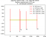
    fm

Manufacture: also from wire (material and diameter are not important). The antenna is flat, like the previous options. For installation on or behind a window. Antenna input impedance 50 Ohm, for use with 50 Ohm cable.


Related publications